
 Tuned intake manifold
First introduced by Mercedes 300SL in 1954, tuned intake manifold is not exactly a new technology. It is discussed here just because its principle is useful to our further study of variable intake manifold.
Before 1950s, engineers believed short intake manifolds were the best to engine breathing. Then they discovered that under some conditions long intake manifolds could actually improve output, thanks to a so-called "supercharging effect". How is that done ? Let's see the following illustration:

Now the interesting thing is: if the inlet valve opens again exactly when the pressure wave comes back, the pressure wave will help charging the combustion chamber due to its high pressure. This is not unlike charging the combustion chamber with a light supercharger, thus we call this supercharging effect.
In order to match the timing of valve opening, the frequency of pressure wave shall synchronize with engine rev, obviously. This frequency is dependent on the length of the intake manifold (L in the figure). The longer the length, the longer the time pressure wave takes to bounce back thus the lower frequency of pressure wave is attained. As a result, a longer intake manifold leads to supercharging effect at lower engine rev. A shorter manifold leads to supercharging effect at higher rev. By selecting a suitable manifold length, we can obtain the desired power characteristic.
Calculations found in order to achieve useful supercharging effect, the intake manifold shall be unusually long. If it is too short, the pressure wave will bounce back and forth too many times in the manifold before the valve opens again, by then the high pressure is largely diminished. Therefore a tuned intake manifold shall be long.
Unfortunately, tuned intake manifold works only across a narrow rev band. If the engine revs beyond that band, the pressure wave will arrive too late in the intake stroke, contributing little to charging. If the engine runs below that rev band, the pressure wave will arrive the inlet valve before it opens. In both cases, the low pressure area of pressure wave may even work against cylinder charging, hampering torque output.
A sports car engine may employ a shorter tuned intake manifold to optimize its output at high rev (in the expense of low to medium rev output). On the contrary, a heavy sedan or commercial van engine may choose a longer manifold to favour low-rpm output at the price of high-rev output. As you can see, the selection of manifold length is always a compromise. That's why many modern engines turn to variable intake manifold...
Variable Intake Manifold (VIM)Variable intake manifold has been popular on naturally aspirated engines since the mid-1990s. It is primarily employed to broaden the torque curve, or in order words, improve the flexibility of engine. Conventional tuned intake manifold focuses on a narrow rev range. In contrast, VIM offers 2 or more stages of intake configuration to deal with different engine speeds. This sounds very much like variable valve timing, but VIM is generally cheaper to produce because it involves only some cast or plastic manifolds and a few electric-operated valves. That explains why it was applied to cheaper and smaller engines well before VVT became popular. Today, many engines employ both features to achieve the best results.
However, variable intake manifold is rarely used on turbocharged or supercharged engines - Volkswagen's 2.0 TFSI engine is one of the few exceptions. This is because forced induction offers a strong supercharging effect already. This largely reduces the benefit of VIM, thus its additional costs and weight are difficult to justify. As more and more cars are switching to turbocharged engines, the popularity of VIM is expected to cool down in the foreseeable future.
There are two kinds VIM: variable length type and resonance type.
Variable length intake manifold (VLIM)Variable length intake manifold is a direct answer to the shortcoming of conventional tuned intake manifold. If a fixed length intake manifold is optimized for a very narrow rev band, why not give it 2 sets of intake manifold, one with short pipes to serve high rpm while another with long pipes to serve low rpm ? By using simple butterfly valves, switching between the long and short pipes are easy.

Some early VLIM systems, like this Ford 2.5 Duratec V6, used separate long and short pipes, which is easily visible here. The short pipes go to the nearest cylinder bank while the long pipes go to the opposite bank. Such arrangement is space engaging. The lack of space leads to narrower pipes used, thus it is not very suitable to high-performance engines.
 3-stage variable length intake manifold
If 2 stages are not good enough to broaden the torque curve, why not use 3 stages ?

The following torque curve shows the effect of the 3 stages of VLIM:

The 3-stage system is a little bit more complicated and space engaging than 2-stage system. It was eventually abandoned when Audi introduced dual-continuous VVT and FSI to broaden the torque curve.
Continuous variable length intake manifold - e.g. BMW DIVABMW's DIVA (Differentiated Variable Air Intake) system was first introduced to the N52 V8 engines on 7-Series in 2001. It is the world's first continuously variable length intake manifold.
The principle is simple. The intake manifold of each cylinder is arranged in circular shape and half-recessed into the V-valley. The inner wall is actually a rotor, on which the air inlet is located. When the rotor swivels, the position of the air inlet moves in relation to the outer housing of manifold. This varies the effective length of the intake manifold, from a maximum 673 mm to 231 mm.
Below 3500 rpm, the DIVA uses the maximum manifold length to optimize low-end torque. Beyond 3500 rpm, the length is reduced gradually according to rev, keeping the supercharging effect at optimum level.

As the DIVA requires a circular construction, it occupies more space (especially height) than other VLIM systems. This prevent it from becoming popular. Even BMW itself was not keen on the technology. When the 4.4-liter V8 was enlarged to 4.8 liters, its extra torque allowed BMW to abandon the DIVA for a simpler 2-stage VLIM system. The next generation V8 even switched to turbocharging, so DIVA has no hope to return. Today, it remains to be the only continuous variable intake manifold ever made to production.
Variable trumpets - e.g. Ferrari F12tdf
Conventional variable intake manifolds are quite weighty and space-engaging. They are also likely to have the intake manifolds twisted or narrowed such that high-end power output is affected. Ferrari F12tdf avoids these problems by adopting a different kind of variable intake manifold. Its V12 engine utilizes 2 sets of trumpets (the black ones in picture below) which can move within the intake plenums, varying the effective length of intake manifolds. The trumpets are moved by hydraulic actuators located between the two plenums. In the F12tdf, the trumpets vary between long and short positions, but theoretically this design can be easily modified to vary continuously between the two positions.

One shortcoming of this design is limited range of adjustment. As the movable trumpets are quite short, the difference beween long and short modes are not as big as conventional VIM systems. However, this problem could be solved by using multiple trumpet sections working in telescopic style.
Resonance intake manifoldBoxer engines and V-type engines may employ resonance intake manifold to broaden torque curve. Each bank of cylinders are fed by a common plenum chamber through separate pipes. The two plenum chambers are interconnected by two pipes of different diameters. One of the pipes can be closed by a valve controlled by engine management system. The firing order is arranged such that the cylinders breath alternately from each chamber, creating pressure waves between them. If the frequency of pressure waves matches the rev, it can help filling the cylinders, thus improved breathing efficiency. As the frequency depends also on the cross-sectional area of the interconnecting pipes, by closing one of them at low rev, the area as well as frequency reduce, thus enhance output at lower rev. At high rpm, the valve is opened thus improves high-speed cylinder filling.

This is the resonance intake system on Porsche 996 GT3. Note that it has 2 pipes connecting between teh 2 plenum chambers.
Resonance intake system has been used in various Porsches starting from 964 Carrera. In 993, Porsche combined it with an additional variable length manifold to form a 3-stage intake system names VarioRam. However, the system is very space consuming (see right hand side picture below), so from 996 forward it reverts to the resonance intake system only, although Porsche keeps using the name VarioRam. Honda NSX is another rare application of the resonance intake system.

Porsche VarioRam system on 993

B: 5000-5800 rpm: long pipes plus short-pipe resonance intake, with one interconnected pipe of the resonance intake closed.
C: above 5800 rpm: long pipes plus short-pipe resonance intake, with both interconnected pipes of the resonance intake opened.
Tuned Exhaust & Variable Back-Pressure ExhaustThe design of exhaust manifold is not unlike intake manifold. Exhaust gas emits in the form of high-pressure pulse. If you have a micro-analysis on the pulse, you will find the pulse is not always high-pressure. In fact, shortly after the first surge of pressure, there is a period of negative pressure (i.e. lower than atmospheric pressure or 1 bar), as shown in the graph below. Why? Because the gas pulse has mass and momentum. To let you easier to understand, imagine the gas pulse as a big truck running on highway and you are standing at the road side. When the truck passes you, your hair is likely to be sucked towards the road, because there is a low-pressure area tailing the truck. The faster the truck runs, the lower pressure is built.

If we can collect the exhaust pulses from all cylinders with equal-length exhaust manifolds (or "header"), we will get an evenly distributed pulse train. Interestingly, this evenly distributed pulse train actually helps sucking exhaust gas out of the combustion chambers, as the low-pressure tail of one pulse sucks the next pulse, so forth. When both intake and exhaust valves are opened during the overlapping period, the aforementioned effect even helps sucking fresh air into the combustion chamber. As a result, this effect is called "reverse-supercharging" or "scavenging".
To make the best use of scavenging effect, an equal-length exhaust manifold is a must. Besides, to reduce the inteference between the exhaust gas pulses from different cylinders, the individual pipes shall be long. This explains why most racing engines and high-performance engines employ tuned exhaust manifolds with very long and strangely routed pipes.

The tuned exhaust manifold (header) on BMW M3 V8. Note the individual pipes before the collector are long and equal-length.
To get the scavenging effect working, the gas flow should run quick enough in the exhaust manifold. Take our truck example again, if the truck is cruising slowly on motorway, there is hardly any vacuum effect you can feel. Exhaust gas pulse is the same. To speed up the gas flow, obviously, the best way is to use narrower exhaust pipes throughout the whole exhaust system - including manifolds, collector and muffler. However, narrower pipes also generate more resistance to gas flow, or what we call "back-pressure". At high rpm where the exhaust gas rate is enormous, the back-pressure will be big enough to outweigh the benefits of scavenging effect. Consequently, narrow exhaust pipes are only benefitial to low rev output. On the contrary, large-diameter exhaust pipes reduce back-pressure at high rpm, boosting top-end power, but at low rpm the exhaust gas flow is too slow to generate scavenging effect, so its output suffers at low rpm.
That is why many performance cars opt for variable back-pressure exhaust. At low rpm, the exhaust gas goes through a narrow path in the muffler, which consists of multiple stages of silencer. This returns relatively high back-pressure, but the narrow path results in high flowing speed, hence good scavenging effect. At high rev, a by-pass valve opens to a second path for the gas to escape, reducing back-pressure and enhance power output.
Principle of variable back-pressure exhaust
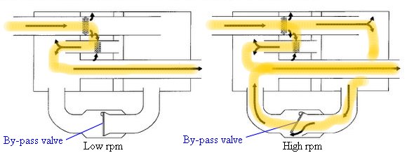
The by-pass also changes the sound quality, making it louder and "sportier". Therefore variable back-pressure exhaust is popular on sports cars.
Copyright© 1997-2011 by Mark Wan @ AutoZine

FUENTE:
http://www.autozine.org/technical_school/engine/Intake_exhaust.html#Tuned-intake

